AT309 Lab #10 Introduction to Processing data withPix4D Software
- Leighton Moorlach

- Dec 3, 2021
- 5 min read
Updated: Mar 22, 2022
Background:
You have processed imagery with Pix4D, and now you will process it with GCPs. You will use the datasets from last week again, but now the GCPs will be part of the workflow. The lab will be very similar to the last one, but now with discussion of GCPs in your workflow.
Objectives:
To import ground control coordinate data into Pix4D.
To understand how to set the coordinate system of the GCP data
To adjust your data in Pix4D using GCP coordinate data
To be understand and compare differences between corrected and non-corrected data
Results:
o What are the 8 steps needed for processing GCPs.
1. Obtain GCPs measurements in the field or through other sources.
2. Add/Import the GCPs with the GCP/MTP Manager without marking them
3. On the menu bar click view > processing. The processing bar appears at the bottom of the main window.
4. Select initial processing and deselect point cloud and mesh and DSM, orthomosaic and index.
5. Click start.
6. Once initial processing is completed, mark the GCPs with the rayCloud.
7. Click process >reoptimize.
8. Regenerate the quality report by clicking process > generate quality report.
o In step 4 of the steps you just wrote down, what must be unchecked before hitting start processing. Why?
You need to process the data first before you add the GCPS and process the DSM and Orthomosaic.
o What needs to be done in Step 7? Why?
You need to reoptimize the data before finishing the process or else it won’t include the GCPs.
o What should be unchecked before engaging in final processing?
Initial processing.
· Before we continue, lets learn a bit more about GCPS. Visit this link to learn more about GCPs: https://support.pix4d.com/hc/en-us/articles/202557489-Step-1-Before-Starting-a-Project-4-Getting-GCPs-on-the-field-or-through-other-sources-optional-but-recommended
o What is the bare minimum number of GCPs to have in a project?
3 GCPs
o What is the recommended number?
5 GCPs
o How many images should contain the GCP?
5 Images
o How should GCPs be placed across the project area?
The GCPs should be placed evenly on the landscape to minimize the error in scale and orientation.
o Is it a good idea to lay them along the edge? Why or why not?
No, they will only be visible in a few images.
· Navigate to the following link: https://support.pix4d.com/hc/en-us/articles/360000276046-How-to-import-and-mark-ground-control-points-GCPs
o Expand the Import GCPs portion:
o What are the 3 types of GCPs?
2D GCP, 3D GCP, Check Point
o How do you change the coordinate system of the GCPs?
Select the coordinate system at the top by clicking edit.
o If your GCPs do not come in properly and show up in the wrong area, what might you need to change?
The order of the coordinates. XYZ or YXZ
o Expand using the RayCloud portion:
o What do the green cross, orange cross, and orange circle mean?
Green cross: Reprojection of the 3D point on the images. Orange cross: Position where the associated 2D key points have been automatically detected. Orange circle: The radius of the orange circle indicates the size of the area that has been taken into account to detect the key point.
o Now exand the Mark/Click on GCPs section:
o Checking the GCPs/MTP box shows what on the right side of the screen?
The GCP Properties and the images associated with that GCP.
o GCPs should be marked on at least how many images?
3-5 images
o What does a pink circle mean?
A pink circle appears when the point is wrongly marked on other images. Outliers are indicated with pink circle and they do not influence the calibration results.
o What NEEDS to be done after marking all the GCPs (Hint: step 9)
Reoptimize
View and add the GCP Information into your folder
· You will need the GCP coordinate information for you to process the GCP tie marker with your data. We will start by copying that information over.
§ Copy the images you and your flight crew members gathered in Week 7, when you engaged in data collection missions over a designated plot at PWA with GCP markers placed.
o Paste that folder into the folder you created within the C:\temp folder for processing.
· We want to start by knowing what kind of data/datum we are working with. In class I showed you the GCP file associated with your mission. I also showed you the projection and coordinate system for that GCP file. The name should be similar to: GCPs_XXXXXX_Nad832011UTM_geoid12b
o Why should files be named with the information in the name?
So the data can be organized properly and recognized by others.
o What is the Geographic Coordinate System?
NAD83(2011) / UTM zone 16N (EGM 96 Geoid)
o What is the Projected Coordinate System?
GCS
o What is the EPSG code?
6345
o What is the Geoid Model?
(EGM 96 Geoid)
o Keep this information in mind when setting the coordinate system of the GCP markers and the output coordinate system.
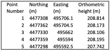
· Generate a table in the space below that contains the point number and the X,Y, and Z variance for each point.

o Which point has the highest variance? Speculate why.
Point 2 has high variance.
o Why might we want to remove this point in our processing?
It could make the data less accurate.
· Now open the GCPs_XXXXXX_Nad832011UTM_geoid12b_simple file.
o Create a table in the space below that contains the information from this table.

o Use the GCPs_XXXXXX_Nad832011UTM_geoid12b_simple when asked to import the GCP markers in your project.
Process the data first without GCPs.
· Before we work with GCPs, we want to first process the data without them.
o I am doing this so in a later lab we can see how much ground control makes a difference with your data.
· In class I provided you with a demonstration on this.
o As a recap, the process is very similar to when you created a 3D model, but instead of choosing a 3D model, you select the map processing template.
· Name your project using the following format datecollected_username_PWAaltitude
o Yellow is information you supply
Reprocess the data, but this time using GCPs
· In the project tab, go to save project as. (See figure 1)
· This is because you will be making a new project, where you now have GCPs correcting the data But this time we will use GCPs in our processing.
o datecollected_username_PWAaltitude_GCP
· Processing Notes. As you process the data, please keep the following pieces of information in mind:
o You must change the default coordinate system to the projected coordinate system the GCP data is in. (hint: if you type in the EPSG number, that coordinate system will load.
o You must set your output to match this coordinate system.
o Use the Ray Cloud to Mark the GCP points. You need not do any more than 4 images per point.
o Remember to remove the 6th GCP point for the reasons you described above.
o Your GCP Manager should look like this (Figure 2):
· Processing Deliverables: For each of the projects that you create, I will be grading you on your ability to demonstrate you processed the data correctly. Make sure you include within this Assignment proper documentation via structure and screen shots showing:
o A labeled section for each of the Sensors listed
o Screen shots showing your use of marking GCPs
§ You should have a screen shot showing the GCPs in the imagery, and the marks you placed for each of the four images you marked per GCP.
§ Make sure to also include images of point 6 and relate to why it needed to be removed.
o In the Geolocation Details of your quality report, there is a ground control point section. Create a series of tables for the ground control points for each of the sensors you processed.
o Along with the document containing answers to this lab, please attach a PDF of each of the quality reports that you generated in the Pix4D processing.
§ Make sure you have a green check box in your quality report that shows you implemented GCPs in your processing (Figure 3).
GCP Table:

Figure 1: GCP Table

Figure 2: Quality report after initial processing.

Figure 3: Quality report after reoptimizing data. Note: PDF quality report is from the final data processing with GCPs included.

Figure 4: GCP #1

Figure 5: GCP #2

Figure 6: GCP #3

Figure 7: GCP #4

Figure 8: GCP #5

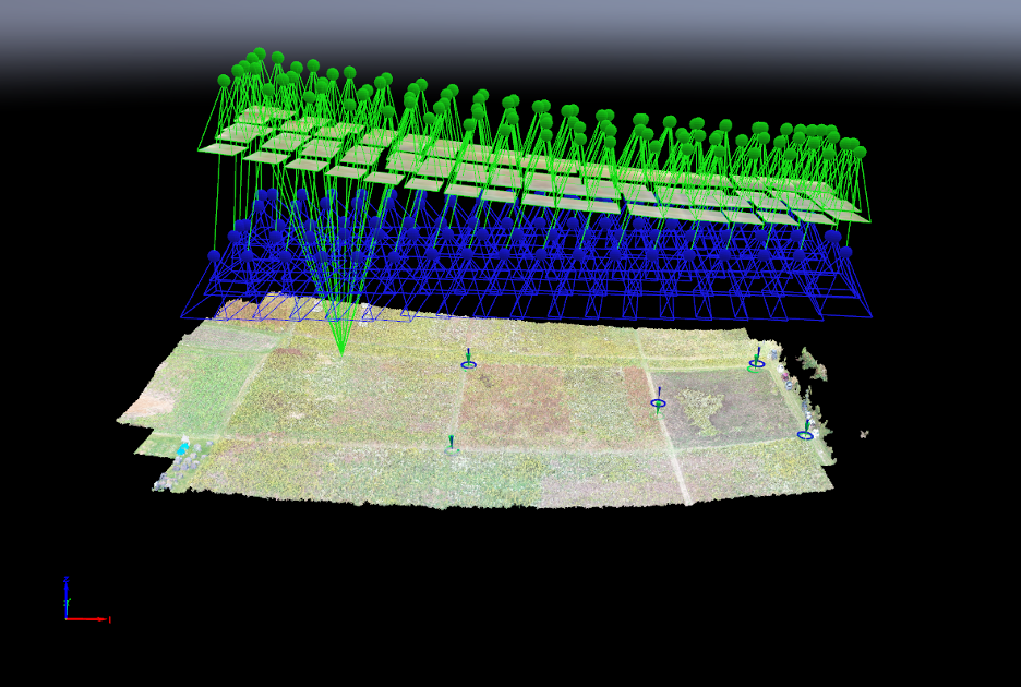
Figure 9: Results of processed data with GCPs included with cameras shown.

Figure 10: Birds eye view of GCPs with cameras off.

Figure 11: Side view with a GCP selected and lines to pictures assigned to that GCP.


Comments